Legacy rectangular prototype and wiring reference
The current selected design is the capsule. Use the capsule STL files and assembly guide. The rectangular 3MF and dimensions below are retained only as the earlier prototype; they are not the newly selected capsule.
These are provisional parts for an eight-pixel light chamber with external electronics. They are not a fitted D1 mini case, a certified electrical enclosure or a sealed/waterproof product. No printer, board dimensions, power supply, strip sleeve dimensions or thermal behavior has been confirmed.
See how it fits together
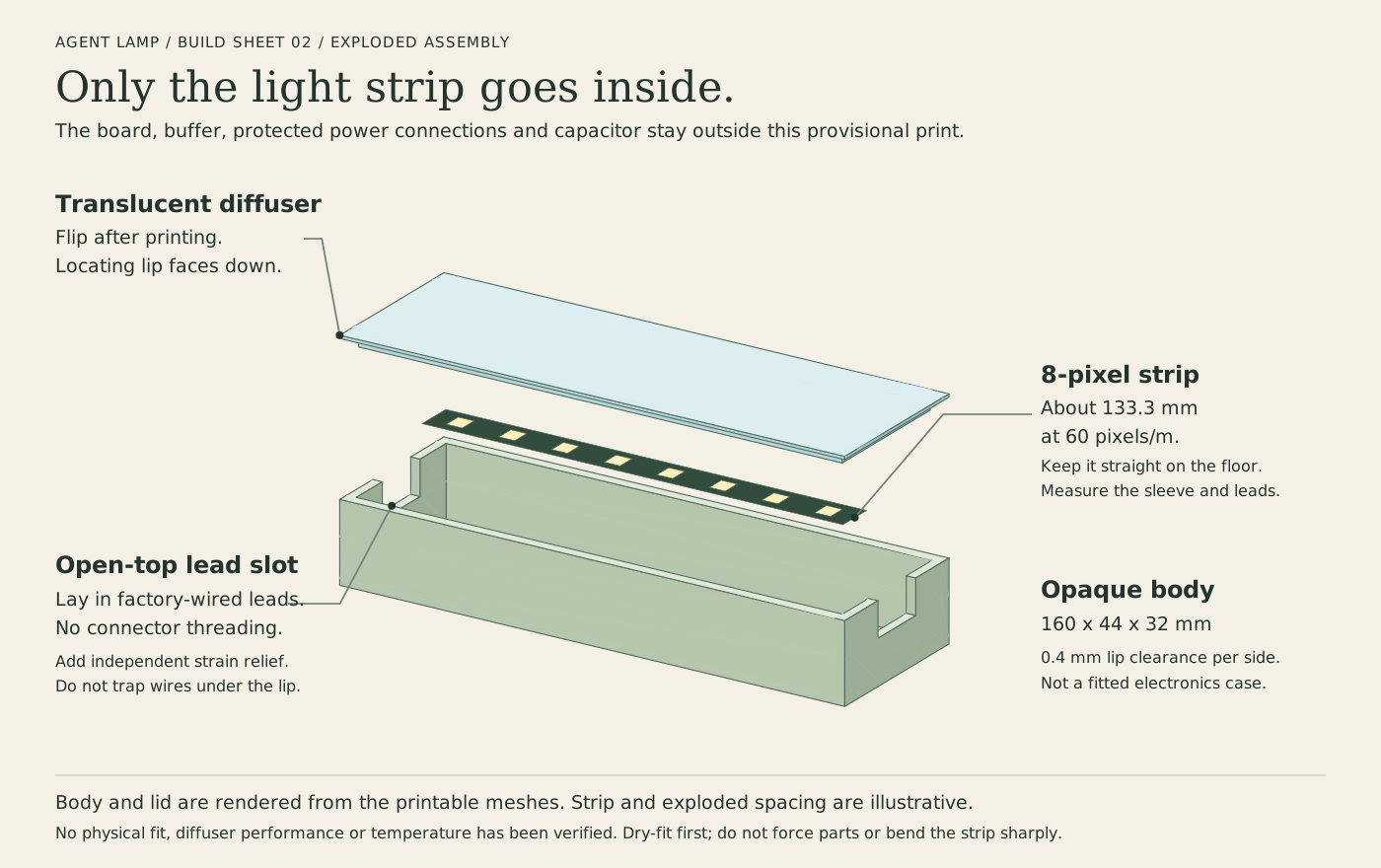
The body and lid illustration comes from the printable meshes. Exploded spacing and the LED strip are illustrative. Only the light strip goes inside this version; keep the controller and protected power connections outside.
Open the enclosure illustration at full size.
See the connections
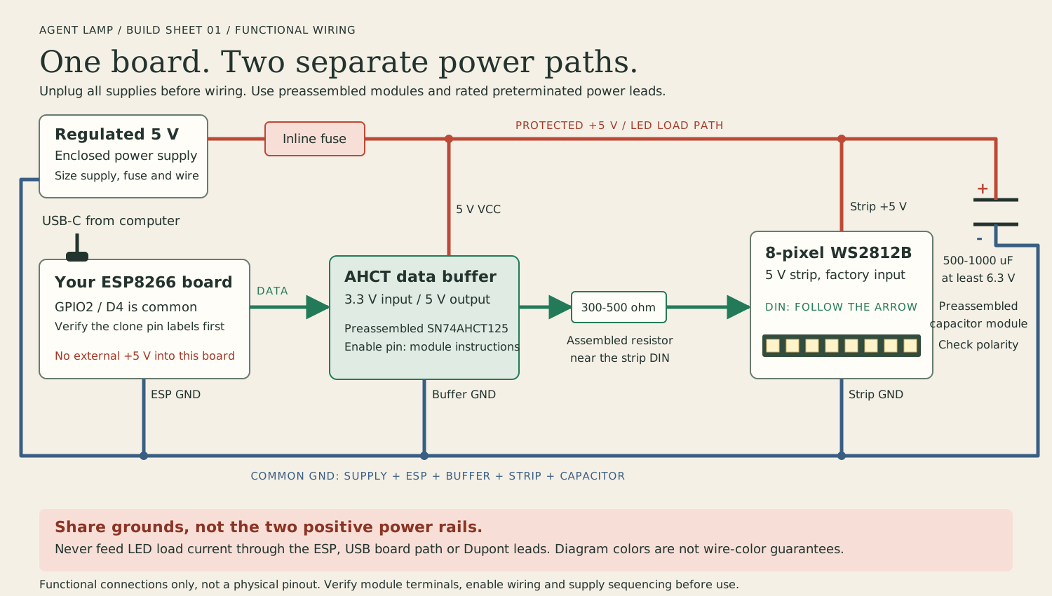
This is a functional wiring map, not your board's pinout. Match the labels to the actual modules before connecting anything. Diagram colors identify circuits, not the colors of your existing wires. Use the separate-USB arrangement shown here only; don't mix it with a single-supply controller's wiring.
Open the wiring diagram at full size.
Build it step by step
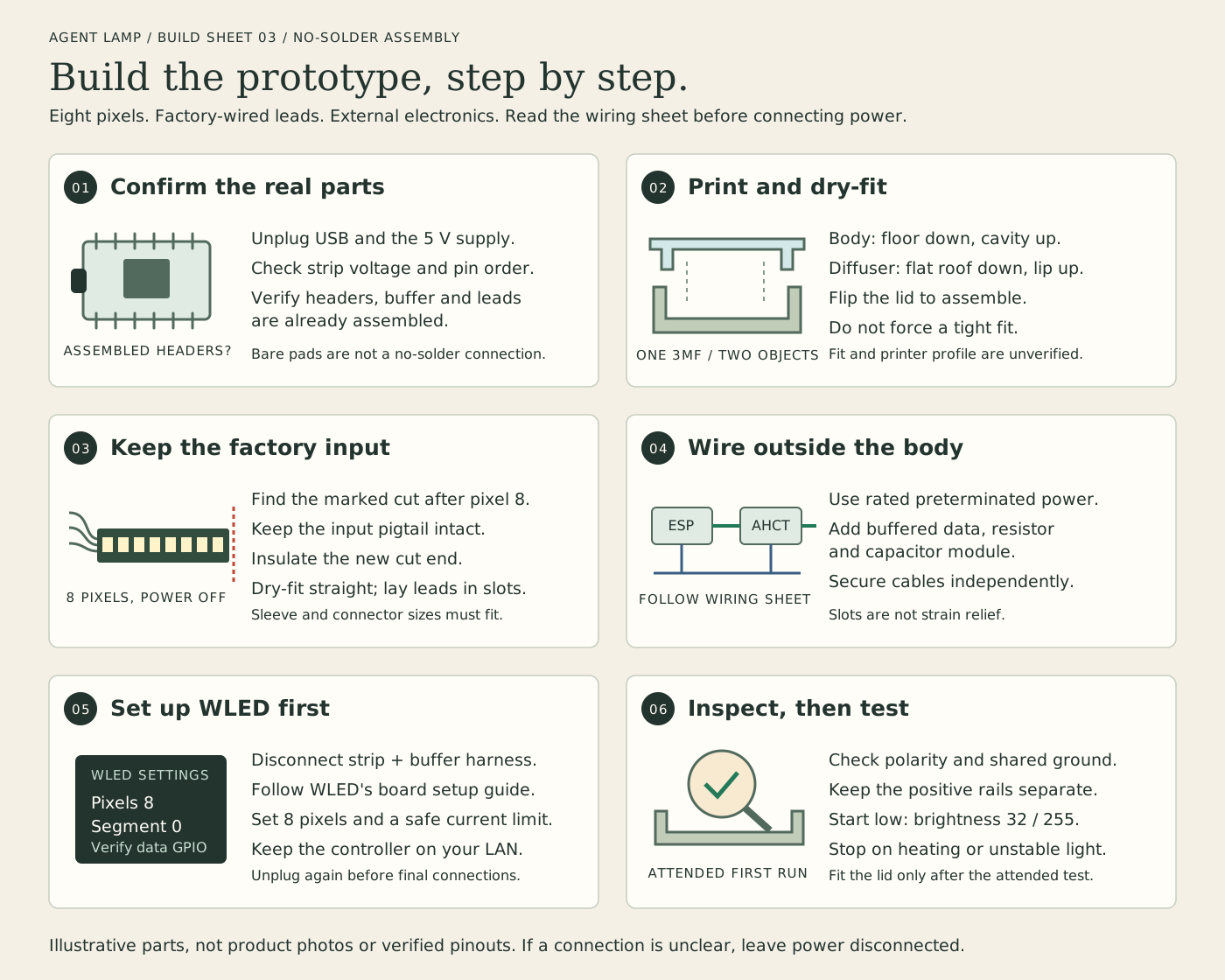
Open the assembly sheet at full size.
- Confirm the parts with all power unplugged. Check the ESP headers are soldered, the strip says 5 V, and you can identify its input
DINand connector pin order. Confirm the buffer, resistor, capacitor and power leads are already assembled. If you have bare pads or an unidentified terminal, stop before wiring and use the photo checklist below. - Open the combined 3MF in your slicer. It contains named body and diffuser objects. Print the body cavity-up and the diffuser roof-down, using the material guidance below. Flip the diffuser over to dry-fit its lip in the body. Check sleeve, lead and lid clearance before applying adhesive.
- Prepare the strip while unplugged. Keep the factory-wired input end, count eight pixels and find the actual marked cut line after the eighth. Cut only there and insulate the new end so exposed pads cannot short. Dry-fit the strip straight on the floor. Lay the flexible leads in an open slot, protect the slot edges, and leave enough room for gentle bends. Do not crease the PCB or force a sleeved strip into the case.
- Assemble the external harness with USB and the strip supply disconnected. Follow the connection diagram and each module's terminal/enable instructions. Route LED load current through rated connectors and protection, not the ESP or jumper wires. Connect the common grounds and buffered data path. Check capacitor polarity. Secure the external cables with independent strain relief so a tug cannot pull the strip or pinch its insulation under the lid.
- Set up WLED with the ESP disconnected from the entire strip/buffer harness. This prevents its data output from feeding an unpowered buffer or strip during USB-only setup. Follow WLED's board-specific setup for your confirmed board. Configure eight pixels, one segment with ID 0, the verified GPIO and a conservative current limit. Follow the bridge setup to select its known private IP and brightness 32. Disconnect USB again before reconnecting the harness.
- Inspect before applying power. Confirm positive and ground terminals, common ground, capacitor polarity, insulation and the separation of USB/external positive rails. Check for shorts and follow your buffer/controller's power-sequencing instructions. Start an attended low-brightness run. Use the bridge's
emit/resolvedcommands from the README to exercise the source colors;npm run demoonly drives the simulator. Disconnect on unexpected heating, smell, flicker or unstable behavior. Secure the strip using its appropriate mounting method and fit the lid only after the attended test, without trapping wires.
Combined print file and dimensions
Download the single body-and-diffuser 3MF. It contains both parts as separate named objects, arranged with a 10 mm gap in print orientation.
If clicking the legacy link opens a Copilot editor instead of Bambu Studio, use File > Import in Bambu Studio or drag cad/print/agent-lamp.3mf from Finder. Keep your own printer/material settings. The current npm run print:open command opens the capsule STLs, not this legacy model.
npm run print:export now creates the capsule STL kit and its current guide. This legacy rectangular 3MF is retained separately and is not included in that kit.
| Object | Dimensions and orientation |
|---|---|
| Agent Lamp body | 160 x 44 x 32 mm. Flat floor down, cavity up. |
| Agent Lamp diffuser | 160 x 44 x 5.2 mm. Broad flat roof down, locating lip up. Flip over to assemble. |
The file uses explicit millimeter units and contains no printer presets, G-code, logos or copied meshes. Assign opaque and translucent filament to the respective objects in your slicer. On a single-material printer, you can select and print each object from this same file in separate runs. The source builds shared-grid boundary meshes and checks closed edges, consistent winding, connected vertex fans and positive volume before export. The package tests read both exported meshes and their non-overlapping placement back. Bambu Studio 02.08.02.60's command-line importer accepts both meshes as manifold. No slicing profile or physical print has been verified.
Default dimensions:
- Body walls 3 mm; floor 2.4 mm; interior 154 x 38 x 29.6 mm.
- Diffuser roof 1.2 mm; lip depth 4 mm; lip wall 1.6 mm.
- Lip outside 153.2 x 37.2 mm, giving 0.4 mm clearance on each side of the body cavity.
- Two open-top end slots, 16 mm wide, start 18 mm above the print bed. With the lid seated, its lip leaves 10 mm of clear slot height below it.
- Assembled height 33.2 mm. The lid rests on the body rim; it is a loose locating lid, not a snap fit or load-bearing retention system.
Lay leads into a slot with the lid removed. There is no need to thread a factory connector through a closed hole. Keep the connector outside if it is too large. Leave the other end slot open for ventilation. Slots are not strain relief: secure the external cable harness independently so pulling a cable does not pull on the strip or move the lamp. Add a removable edge sleeve/grommet appropriate to your cable, or smooth the printed slot edges. Never crush insulation between the lip and body.
At 60 pixels/m, eight pixel pitches occupy approximately 133.3 mm. Measure the actual cut marks. The 154 mm cavity length allows about 20.7 mm extra total, not an unlimited connector/bend allowance. The 38 mm width allows a provisional sleeve envelope up to 16 mm wide with side space, but that is a design assumption, not a measured property of B09DT6SDKC. An IP67 sleeve, end seal, factory lead boot or adhesive channel can need more room.
Place the strip straight along the long floor. Do not fold the flexible PCB sharply or bend it sideways. Route only its flexible leads toward the end slots, respecting the actual wire/sleeve bend radius. If the lead boot or a gentle loop cannot fit, increase the dimensions in cad/parameters.json and regenerate before printing. Do not force the part shut.
The roof-down diffuser orientation and open-top body slots avoid enclosed bridging in the model. Inspect first-layer coverage, thin walls and any slicer-generated supports in your own slicer. A 0.4 mm nozzle, roughly 0.2 mm layers and at least three perimeters are reasonable starting settings, not a tested profile. Print a small clearance sample before spending time on the full lid. Long parts may warp; don't solve a tight fit by forcing brittle walls.
Use opaque PETG for the body and natural/translucent PETG for the diffuser if your printer supports them. Opaque white inside the chamber reflects light. PLA is suitable only for an attended low-temperature fit/light test; it softens at modest temperatures and is not a fire barrier. Material choice, pigment and layer settings change diffusion. Printed plastic provides no electrical fire rating. Don't leave the first powered tests unattended or put mains wiring inside.
Confirm your usable bed fits the combined 160 x 98 mm footprint plus brim and margins, or print one object at a time with a 160 x 44 mm footprint. Regenerate with:
python3 cad/generate.py
python3 cad/visualize.py
python3 -m unittest discover -s cad -p 'test_*.py'
A no-solder parts path
The enclosure does not require soldered mechanical assembly. Electrical assembly can also avoid soldering if the modules and leads arrive preassembled. Bare ESP pin pads or a bare LED cut end cannot connect themselves.
Prefer reusing your USB-C ESP8266 clone. To do that without soldering, confirm it already has soldered headers and choose a compatible preassembled terminal/socket carrier plus preassembled SN74AHCT125 buffer module. A bare breakout board or loose pin headers are not a no-solder kit. Do not rely on loose pins pushed through unsoldered holes.
If the board has bare pads, either have someone competent assemble it or use an already-assembled board/controller. A complete WLED controller is an optional fallback, not a required replacement for your ESP. Choose one explicitly rated for 5 V WS2812B, with a suitable 5 V data buffer, data resistor and screw/pluggable terminals already assembled. Verify its power-input voltage; many LED controllers instead require a higher voltage.
| Item | What to look for |
|---|---|
| Eight-pixel WS2812B section | Prefer the factory-wired leading end of your 5 V strip, keeping its connector and leads intact. With power disconnected, cut only at the marked cut line after pixel eight. Insulate/seal the unused cut end. |
| Strip connector | A matching factory 3-pin pigtail with correct pinout. If using a clip instead, it must match the exact strip width, copper-pad layout and sleeve type. Generic clips often do not fit IP67 sleeves reliably. |
| Low-voltage supply | Enclosed, regulated 5 V supply with a compatible factory plug; 2 A is a reasonable candidate for this short prototype, subject to the selected controller and wiring. No exposed mains terminals. |
| Power distribution | Rated screw terminals or lever connectors suited to the wire gauge, precrimped/ferruled leads where appropriate, and an appropriately chosen inline fuse/protection close to the supply. Follow connector specifications; don't tin wires going under screw terminals. |
| Data buffer | SN74AHCT125-class 3.3 V to 5 V buffer with terminals/headers already assembled. Generic bidirectional I2C shifters are not substitutes. Ensure its enable/input pins follow the module's instructions. |
| Data resistor | Preassembled inline 300-500 ohm resistor lead/module near the strip DIN if the chosen controller does not already provide it. |
| Bulk capacitor | Preassembled insulated 500-1000 microfarad capacitor module, at least 6.3 V rated, near the strip power input. Observe polarity. Avoid exposed loose capacitor legs in connectors not rated to hold them. |
| Protective details | Suitable cable gauge, insulated connectors, strain relief, smooth/grommeted slots and a safe nonconductive external mounting arrangement. |
Color coding and JST-style connector shapes do not guarantee matching pinouts. Check actual 5V, GND and DIN markings and the connector pin assignments. If the strip arrives with no usable prewired input, don't assume a clip is adequate; use a compatible preterminated segment or have the connection assembled. That may require buying parts.
Wiring limits
Disconnect every supply while making connections. Start with eight LEDs, not the entire 300-pixel roll.
For the existing board with separate USB board power and strip power, the signal path is:
ESP GPIO, often D4/GPIO2
    -> preassembled 3.3 V to 5 V AHCT data buffer
    -> 300-500 ohm series resistor near strip
    -> strip DIN

Regulated 5 V strip supply -> protection -> strip 5 V
                                      -> buffer 5 V
Strip supply GND <-> strip GND <-> buffer GND <-> ESP GND
Capacitor module across strip 5 V and GND, correct polarity
ESP board powered independently by USB-C
Common ground is required. Do not join the separate supply's positive rail to the USB-powered board's 5 V pin or backfeed USB. Never apply 5 V to ESP GPIO. Follow the buffer/controller's supply and data sequencing guidance to avoid phantom powering. A single-supply integrated controller has different wiring; use its manufacturer's rated terminals and power instructions rather than mixing these two arrangements.
Plan conservatively for up to 60 mA per pixel at full white: eight pixels is 0.48 A; 300 pixels would be 18 A. These are design bounds, not a measurement of your strip. Keep LED load current on rated preterminated power paths, not through the D1 mini, its USB path, GPIO, a breadboard or Dupont jumper contacts. Low-current signal connections are separate. Low brightness, WLED current limiting and a plastic enclosure do not replace appropriate conductors, protection and connections.
Check polarity and shorts before power-up. Begin at the bridge default brightness 32 and a conservative WLED current limit. Observe the board, buffer, connectors, strip and enclosure for heating during an attended test. Disconnect on unusual warmth, smell, flicker or unstable operation. Do not close up an assembly that has not been checked. The slots provide an opening for air, not a proven cooling capacity.
Still to confirm
The printer's usable bed, nozzle and supported materials; actual board dimensions and soldered headers; strip voltage/pitch/sleeve/connector pinout; selected preassembled controller or buffer; available power supply and protection; cable dimensions; strain relief; lid clearance; brightness and temperature under continuous use. This design deliberately leaves the electronics outside until those choices are known.
Before buying connectors or wiring, collect clear photos of both sides of the ESP board showing its pin labels and soldered headers; the strip's input pigtail, connector and 5V/GND/DIN marks; and the supply's output-voltage/current label and plug. Measure the board/header spacing, strip PCB width and sleeved width/thickness, eight-pixel cut length, lead-boot length, and cable diameter. These checks determine whether the no-solder path works with the parts already on hand.